2016年4月20日 星期三

CC3D Atom 外加 氣壓計+羅盤 -> Clean flight


Firmware 刷 INAV 1.1RC2

另外補充 刷這版軟體 接收機要用PPM 模式比較好,接腳功能才會全開, 尤其是CC3D 一定要用PPM


Quick summary of main features:
- Legacy BARO, SONAR, GPS PH, GPS RTH modes are removed and replaced by ALTHOLD, POSHOLD and RTH modes
- Gyro and accelerometer FIR filtering
- Quaternion IMU logic for Level modes. More precision, less drift and faster performance
- Advanced INS/GPS position estimation for best accuracy
- Advanced accelerometer and magnetometer calibration
- Smart RTH (return to home) that would use the safe altitude to return home - avoid the trees and buildings - and land
- RTH on failsafe (radio signal loss)
- Waypoints and fully autonomous missions (work in progress)

iNav has different config settings and simply restoring old backup will result in poor performance!

Please read the docs before you go fly iNav for the first time:
Advanced accelerometer calibration
CLI variable reference
GPS Failsafe and Glitch Protection
Navigation modes

iNav on GitHub:
https://github.com/iNavFlight/inav

Documentation:
https://github.com/iNavFlight/inav/wiki

Firmware builds:
https://github.com/iNavFlight/inav/releases


===============================================================

Advanced accelerometer calibration

Konstantin Sharlaimov edited this page on 30 Jan · 9 revisions
Accelerometer calibration is mandatory if inertial position estimation is used. Modern accelerometer sensors are accurate, but they require calibration if we want precise measurements. Sensors might be biased, gains on different axis might be different. Advanced 6-point calibration takes care of all irregularities sensor might have.

Accelerometer calibration steps

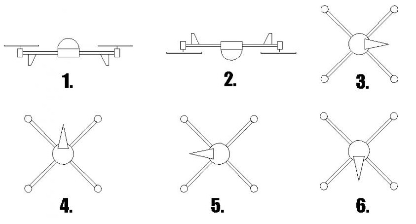
  1. Connect the copter to the "Configurator" software, select the "Setup" tab.
  2. Place copter level (pos 1) and press "Calibrate Accelerometer" button. Advanced calibration has been activated and recorded the 1-st data point.
  3. Place copter on all sides in sequence (pos 2-6): on its back, right side, nose up, left side, nose down. Press "Calibrate Accelerometer" button for in every position. The advanced calibration algorithm will record 2-nd to 6-th data points.
  4. After all 6 positions have been recorded advanced calibration will calculate offsets and gains and store them in EEPROM. Accelerometer calibration done.
  5. Use CLI to verify that accgain_xaccgain_y and accgain_z parameters are NOT ZERO. If they are, algorithm failed to converge, calibration failed and needs to be repeated.
There is no need to place copter perfectly aligned, the algorithm does not care about exact positions as long as they are close to 90 degree apart and copter is stationary in every position.

Level calibration

Proper accelerometer calibration does not guarantee copter being level. Chip might be misaligned on board or the board itself might be mounted at some tiny angle. For level flight and navigation features to work you need to trim the firmware to level flight using "Board Alignment" on the "Configuration" tab.
NOTE! Unlike in "official" Cleanflight firmware board alignment angles are set in degrees*10, so if you need to trim your board 1.5 degrees you should enter "15".
NOTE2! To keep things compatible with official Configurator, angles more than 36 deg and less than -18 deg can only be set through CLI parameters: align_board_pitchalign_board_roll andalign_board_yaw.
This applies to mounting the flight controller at 90 degree to keep USB port accessible. You have to set align_board_yaw=900 from CLI.

Backup and restore the settings

To avoid going through full calibration after resetting the configuration new CLI settings are introduced to get and set accelerometer offsets and gains: acczero_xacczero_yacczero_z,accgain_xaccgain_yaccgain_z.

iNav CLI variables

oleost edited this page 7 days ago · 28 revisions
Cleanflight CLI variables related to navigation features
General/Shared Variables
VariableDescription/UnitsMinMax
align_magWhen using an external magnetometer sensor this should be set to actual sensor alignment relative to board. Values: DEFAULT, CW0, CW90, CW180, CW270, CW0FLIP, CW90FLIP, CW180FLIP, CW270FLIP
align_board_rollBoard alignment on ROLL axis (deg * 10)-18003600
align_board_pitchBoard alignment on PITCH axis (deg * 10)-18003600
align_board_yawBoard alignment on YAW axis (deg * 10)-18003600
gps_providerGPS hardware type: NMEA, UBLOX, NAZA, I2C-NAV
gps_nav_modelGPS navigation model: LOW_G (Pedestrian), HIGH_G (Airborne<4G). Currently supported only of Ublox GPS modules. HIGH_G may increase accuracy, especially on fast and agile airplanes, but it requires much better satellite signal quality. Safe default is "LOW_G".
failsafe_procedureFailsafe type: SET-THR - set throttle tofailsafe_throttle, RTH - execute RTH sequence if possible, land otherwise
max_angle_inclination_rllMaximum inclination in level mode (ROLL axis)100900
max_angle_inclination_pitMaximum inclination in level mode (PITCH axis)100900
inav_accz_unarmedcalControls if inertial position estimator should compute gravity offset on accelerometer Z-axis dynamically when drone is unarmed. Mostly affects accuracy of altitude estimation and althold performace. No real reason to disable this feature.OFFON
inav_use_gps_velnedDefined if iNav should use velocity data provided by GPS module for doing position and speed estimation. If set to OFF iNav will fallback to calculating velocity from GPS coordinates. Using native velocity data may improve performance on some GPS modules. Some GPS modules introduce significant delay and using native velocity may actually result in much worse performance. Safe default is "OFF"OFFON
inav_gps_delayGPS position and velocity data usually arrive with a delay. This parameter defines this delay. Default should be reasonable for most GPS receivers.0500
inav_gps_min_satsMinimum number of GPS satellites in view to consider GPS position valid. Some GPS receivers appeared to be very inaccurate with low satellite count.510
inav_w_z_baro_p010
inav_w_z_gps_p010
inav_w_z_gps_v010
inav_w_xy_gps_p010
inav_w_xy_gps_v010
inav_w_xy_dr_v010
inav_w_z_res_v010
inav_w_xy_res_v010
inav_w_acc_bias01
inav_max_eph_epv09999
inav_baro_epv09999
nav_alt_p
nav_alt_i
nav_alt_d
nav_vel_p
nav_vel_i
nav_vel_d
nav_navr_p
nav_navr_i
nav_navr_d
nav_use_midrc_for_altholdOFFON
nav_disarm_on_landingOFFON
nav_extra_arming_safetyIf set to ON drone won't arm if no GPS fixOFFON
nav_user_control_modeDefines how Pitch/Roll input from RC receiver affects flight in POSHOLD mode: ATTI - right stick controls attitude like in ANGLE mode; CRUISE - right stick controls velocity in forward and right direction.
nav_position_timeoutIf GPS fails wait for this much seconds before switching to emergency landing mode (0 - disable)010
nav_wp_radiusWaypoint radius. Waypoint would be considered reached if machine is within this radius1002000
nav_max_speedMaximum velocity firmware is allowed in full auto modes (POSHOLD, RTH, WP)102000
nav_manual_speedMaximum velocity firmware is allowed when processing pilot input for POSHOLD/CRUISE control mode
nav_manual_climb_rateMaximum climb/descent rate firmware is allowed when processing pilot input for ALTHOLD control mode
nav_pos_hold_deadband10250
nav_alt_hold_deadband10250
nav_min_rth_distance
nav_rth_alt_modeAltitude control mode: CURRENT, EXTRA, FIXED, MAX, AT_LEAST
nav_rth_altitude
gyro_soft_lpf_hzSoftware-based filter to remove mechanical vibrations from the gyro signal. Value is cutoff frequency (Hz). For larger frames with bigger props set to lower value. Default 60Hz0200
acc_soft_lpf_hzSoftware-based filter to remove mechanical vibrations from the accelerometer measurements. Value is cutoff frequency (Hz). For larger frames with bigger props set to lower value. Default 15Hz0200
baro_use_median_filter
magzero_x
magzero_y
magzero_z
acczero_x
acczero_y
acczero_z
accgain_x
accgain_y
accgain_z
Multirotor
VariableDescription/UnitsMinMax
nav_mc_bank_angleMaximum banking angle (deg) that multicopter navigation is allowed to set. Machine must be able to satisfy this angle without loosing altitude1545
nav_mc_hover_thrMulticopter hover throttle hint for altitude controller. Should be set to approximate throttle value when drone is hovering.10002000
nav_mc_min_fly_thrMax throttle value treated as one of the conditions for landing detection. Must be sufficiently low to guarantee the "not flying" state even with full battery, but high enough for Altitude Hold controller to reach it.10002000
throttle_tilt_comp_strCan be used in ANGLE and HORIZON mode and will automatically boost throttle when banking. Setting is in percentage, 0=disabled.0100
nav_pos_pControls how fast the drone will fly towards the target position. This is a multiplier to convert displacement to target velocity
nav_pos_iControls deceleration time. Measured in 1/100 sec. Expected hold position is placed at a distance calculated as decelerationTime * currentVelocity
nav_pos_d
nav_posr_pP gain of Position-Rate (Velocity to Acceleration) PID controller. Higher P means stronger response when position error occurs. Too much P might cause "nervous" behavior and oscillations0255
nav_posr_iI gain of Position-Rate (Velocity to Acceleration) PID controller. Used for drift compensation (caused by wind for example). Higher I means stronger response to drift. Too much I gain might cause target overshot0255
nav_posr_dD gain of Position-Rate (Velocity to Acceleration) PID controller. It can damp P and I. Increasing D might help when drone overshoots target.0255
Fixed-Wing

VariableDescription/UnitsMinMax
nav_fw_cruise_thr
nav_fw_min_thr
nav_fw_max_thr
nav_fw_bank_angle
nav_fw_climb_angle
nav_fw_dive_angle
nav_fw_pitch2thr
nav_fw_roll2pitch
nav_fw_loiter_radius


GPS Failsafe and Glitch Protection

RiceCakeWtf edited this page 2 days ago · 7 revisions

Overview

GPS Systems can occasionally drop the signal (lose FIX) or provide significantly inaccurate position information (glitch). While errors are more likely in conditions where the GPS signal can bounce off multiple paths before reaching the receiver (multipathing), errors can occasionally occur even with clear sky.
Without updates from GPS System, the inertial position estimation allow approximately 1.5 seconds of position information but after this the horizontal position drift becomes so large that the horizontal position cannot be maintained at all. At this point the position estimator will report invalid position to the navigation core. If you still have RC radio control it is recommended to take back control using ANGLE, HORIZON, ALTHOLD or ACRO as soon as possible.
Action taken on invalid position is dependent on current flight mode.

GPS glitch protection

Sometimes GPS provides very inaccurate position information despite having the fix and the good satellite count. This event is usually called a "GPS glitch". iNav has logic to detect and ignore inaccurate/inconsistent GPS position updates. Glitches are detected by comparing the new position update received from the GPS unit with a position projected out from the previous update's position and velocity.
The new GPS position is accepted as “good” if:
  1. the two positions are within the hard coded INAV_GPS_GLITCH_RADIUS (currently 2.5m)
  2. the new position is within a radius that is 10m/s/s (INAV_GPS_GLITCH_ACCEL) * dt * dt. Where “dt” is the time difference between the two GPS samples.
GPS glitches are treated by the position estimator in the same way as losing GPS fix.
At the moment the code is experimental and "glitched" GPS positions are not ignored.

Action taken on invalid position event

ANGLE, HORIZON, ACRO, ALTHOLD mode

These modes are not GPS-dependent, nothing will happen but you will be unable to switch into an autopilot flight mode (POSHOLD, RTH, WP) until the failure clears.

POSHOLD mode

The copter will be forced into ANGLE mode, pilot will have complete control over copter attitude. If ALTHOLD mode was selected it will remain active. When failure clears POSHOLD more will resume.

RTH and WP modes (including failsafe RTH)

RTH and WP are considered full-auto modes. It is assumed that pilot might have no control over the copter so the safest action in case of invalid position is landing the machine. Copter will enter Emergency Landing state if failure is consistent for over 2 seconds.

Emergency Landing

In case of critical failure, Emergency Landing is triggered. In Emergency Landing state copter is forced into ANGLE mode, ROLL and PITCH input is centered to maintain level, pilot stick input is ignored and copter enters a controlled descent.
While Emergency Landing is active pilot is unable to switch into ALTHOLD, POSHOLD, RTH or WP mode. If pilot wants to regain control of the copter he should switch to ANGLE, HORIZON or ACRO more.

Tips to improve GPS reception and avoid GPS outages and glitches

  1. Place the GPS module on the outside of your vehicle (in an elevated position or on a mast if appropriate) with a clear view of the sky.
  2. If GPS module is combined with a compass sensor, place it as far as possible from the motors, ESCs and power wires (at lest 10 cm)
  3. 1.2-1.3 GHz FPV video transmitters are know to be interfering with GPS reception. If you use such transmitter place it as far as possible from GPS module and expect some degradation in GPS quality
  4. Select a GPS module with biggest GPS antenna. Bigger GPS antenna - better reception.
  5. Use a two-system receiver is possible. For example uBlox NEO-M8N is GPS/GLONASS capable receiver. More systems means better noise resistance, more satellites, better accuracy.


Ref : http://www.rcgroups.com/forums/showthread.php?t=2495732

沒有留言:

張貼留言