2016年4月22日 星期五
2016年4月21日 星期四
apm setup
必要硬體設定
在初次設定中,其中一步就是您必須使用Mission Planner來設定一些必要的硬體組件,此頁面將詳細介紹您選擇機架方向、設定RC搖控器/接收機、及校正羅盤及加速度計的流程。
選擇機架類型
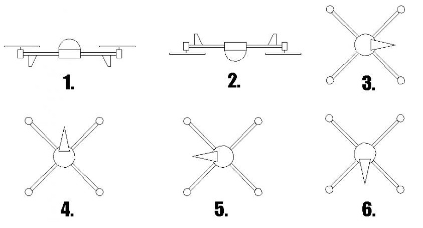
在Mission Planner的Initial Setup畫面中選擇Mandatory Hardware > Frame Type。選擇對應您飛行器的機架類型。而方向的話預設的情況下是設定為X,如果您想讓其中一個機臂朝向前方請選擇Plus(+)的設定,對於三軸飛行器(Tricopter)、傳統直升機及Y6,是不理會機架類型的。

(如果是H型機架的四軸飛行器請在Advanced Parameter頁籤中將此選項設為3,並且為了使用H型機架的架構將左後方及右後方的螺旋槳交換,同時反轉這兩個馬達的旋轉方向(透過交換馬達的兩根線),並將前面兩個馬達也使用同樣步驟操作。
校正羅盤
要執行基礎的羅盤校正請跟隨下列步驟:
- 在Intial Setup > Mandatory Hardware選擇Compass,並選擇您羅盤擺放位置的正確設定。
- 請確定Enable及AutoDec的核選方塊已勾選。
- 點選 “Live Calibration” 按鈕。
- 下一步請選擇您飛控的設定,如果是Pixhawk或是PX4請選擇有Pixhawk圖片的Pixhawk/PX4的選項。如果是APM2.6請選擇有GPS+羅盤模組圖片的APM with External Compass選項,這些選項將會自動幫您輸入對應您飛控板的正確數值,請確定您在安裝GPS+羅盤模組時,上面的箭頭是與飛控上的前頭一樣朝著飛行器的正前方。

- 這時將會彈出一個視窗告知您有60秒的時間來將APM/PX4繞著所有的軸向來旋轉,請點選"OK"。
- 接著會有一個顯示Mission Planner正在收集羅盤資料的倒數計時畫面。
- 接著在這60秒內您必須抓住您的飛行器在控中慢慢的旋轉讓每一面(前方、後方、左方、右方、上方及下方)都朝著地面數秒鐘。

- 當完成之後會有另一個視窗彈出告知您它所計算出來的新差異值。
- 在APM上,只要全部的三個值都介於-150到150之前就表示這些值正常,請點選"OK"。
- 註,在PX4及Pixhawk上這三個值必須比150大或小於-150,請點選OK。
可人觀看這個影片是一個羅盤校正的範例。
關於更詳細的羅盤校正及其它設定如"compassmot(*)“的設定程序可以在這裡(*)找到。
有關磁力干擾的原因跟減少方法可以在這裡(*)找到。
校正加速度計
在Initial Setup裡從左側選單選擇Accel Calibration。
如果你是使用ArduCopter以上請確定您已勾選AC 3.0+的核取方塊。而如果您是使用2.9.1b(或更早的版本),請不要勾選此核取方塊。在此程序中您須要在過程中將飛行器如下圖所示的每一面依次擺好飛行器,此步驟中的水平位置是否正確是非常重要的,因為這將是飛控在飛行過程中控制您水平姿態的依據。
請不要在每一個步驟按下按鍵後立即移動您的飛行器,要如何放置並保持飛行器可以觀看此影片的範例。

如果您已經準備好要校正了請按下Calibrate Accel。

Mission Planner會提示彈出對話框告知您將飛行器放置各個校正方向,過程中會告知您須要放置的方向。(無須一定要去點選Click When Done按鈕)

當Mission Planner如下圖所示的顯示 “Calibration Successful!"表示您已完成了校正程序。

校正搖控器
打開搖控器並確認搖控模式為飛機(APM不管您是使用哪一種平台來飛行,都必須是使用飛機模式),並且將所有的微調(trim)調回中點。

Mode 1搖控器(日本手),是使用左邊搖桿來控制pitch跟yaw,右邊搖桿則是油門跟roll。
Mode 2搖控器(美國手),是使用左邊搖桿來控制油門跟yaw,古邊搖桿則是pitch跟roll。
無論是哪一種搖控器、其中一個三段開關應該設為通道5來控制飛行模式。
另外也可以將旋鈕設為通道6來做為飛行中調參使用,而通道7跟通道8可以設為開關做它其額外的功能。
點選Mission Planner畫面右下方的"Calibrate Radio"按鈕,Mission Planner將會呼叫一個對話框來提醒您是否打開搖控器、電池是否確定沒有接上以及槳是否已拆下。點選OK即可繼續。

點選OK之後,移動搖控器的搖桿及切換開關到各自的移動極限並觀察搖控校準條的結果。在校準條上將會出現紅色的線以標示行程的最大及最小值,最後切換通道5開關及旋轉通道6的旋鈕來確認它們的移動範圍(通道7及通道8在基礎操作中用不到)。
您的搖控器應該要改變成如下的方向:
通道1 : 低位=roll 向左 ; 高位=roll向右。
通道2 : 低位=pitch向前 ; 高位=pitch向後。
通道3 : 低位=油門減少(關閉) ; 高位=油門增加。
通道4 : 低位=yaw向左 ; 高位=yaw向右。
通道1 : 低位=roll 向左 ; 高位=roll向右。
通道2 : 低位=pitch向前 ; 高位=pitch向後。
通道3 : 低位=油門減少(關閉) ; 高位=油門增加。
通道4 : 低位=yaw向左 ; 高位=yaw向右。

當roll、pitch、油門、yaw及通道5(及可選的通道6、7、8)的校正條上的紅線都設定到各自的最低位及最高位後請點選Click when Done。Mission Planner將會顯示一個校正資料結果的訊息視窗,通常值會落在最小1100及最大1900之間。如果校正條的方向與您搖控器搖桿移動的方向相反代表該通道在您搖控器上設的了反向。可以使用搖控器的通道反向功能來在搖控端將它們轉向到正確的方向。(如果您對這步驟不熟悉可以查看您搖控器材的說明書來設定)

cleanflight code study 00
// mw.c
void taskMainPidLoop(void)
{
cycleTime = getTaskDeltaTime(TASK_SELF);
dT = (float)cycleTime * 0.000001f;
// Calculate average cycle time and average jitter
filteredCycleTime = filterApplyPt1(cycleTime, &filteredCycleTimeState, 1, dT);
debug[0] = cycleTime;
debug[1] = cycleTime - filteredCycleTime;
imuUpdateGyroAndAttitude();
annexCode();
if (rxConfig()->rcSmoothing) {
filterRc();
}
#if defined(BARO) || defined(SONAR)
haveProcessedAnnexCodeOnce = true;
#endif
#ifdef MAG
if (sensors(SENSOR_MAG)) {
updateMagHold();
}
#endif
#if defined(BARO) || defined(SONAR)
if (sensors(SENSOR_BARO) || sensors(SENSOR_SONAR)) {
if (FLIGHT_MODE(BARO_MODE) || FLIGHT_MODE(SONAR_MODE)) {
applyAltHold();
}
}
#endif
// If we're armed, at minimum throttle, and we do arming via the
// sticks, do not process yaw input from the rx. We do this so the
// motors do not spin up while we are trying to arm or disarm.
// Allow yaw control for tricopters if the user wants the servo to move even when unarmed.
if (isUsingSticksForArming() && rcData[THROTTLE] <= rxConfig()->mincheck
#ifndef USE_QUAD_MIXER_ONLY
#ifdef USE_SERVOS
&& !((mixerConfig()->mixerMode == MIXER_TRI || mixerConfig()->mixerMode == MIXER_CUSTOM_TRI) && mixerConfig()->tri_unarmed_servo)
#endif
&& mixerConfig()->mixerMode != MIXER_AIRPLANE
&& mixerConfig()->mixerMode != MIXER_FLYING_WING
#endif
) {
rcCommand[YAW] = 0;
}
if (throttleCorrectionConfig()->throttle_correction_value && (FLIGHT_MODE(ANGLE_MODE) || FLIGHT_MODE(HORIZON_MODE))) {
rcCommand[THROTTLE] += calculateThrottleAngleCorrection(throttleCorrectionConfig()->throttle_correction_value);
}
#ifdef GPS
if (sensors(SENSOR_GPS)) {
if ((FLIGHT_MODE(GPS_HOME_MODE) || FLIGHT_MODE(GPS_HOLD_MODE)) && STATE(GPS_FIX_HOME)) {
updateGpsStateForHomeAndHoldMode();
}
}
#endif
// PID - note this is function pointer set by setPIDController()
pid_controller(
pidProfile(),
currentControlRateProfile,
imuConfig()->max_angle_inclination,
&accelerometerConfig()->accelerometerTrims,
rxConfig()
);
mixTable();
#ifdef USE_SERVOS
filterServos();
writeServos();
#endif
if (motorControlEnable) {
writeMotors();
}
#ifdef USE_SDCARD
afatfs_poll();
#endif
#ifdef BLACKBOX
if (!cliMode && feature(FEATURE_BLACKBOX)) {
handleBlackbox();
}
#endif
}
src/main/flight/Imu.c
static void imuCalculateEstimatedAttitude(void)
{
static filterStatePt1_t accLPFState[3];
static uint32_t previousIMUUpdateTime;
float rawYawError = 0;
int32_t axis;
bool useAcc = false;
bool useMag = false;
bool useYaw = false;
uint32_t currentTime = micros();
uint32_t deltaT = currentTime - previousIMUUpdateTime;
previousIMUUpdateTime = currentTime;
// Smooth and use only valid accelerometer readings
for (axis = 0; axis < 3; axis++) {
if (imuRuntimeConfig->acc_cut_hz > 0) {
accSmooth[axis] = filterApplyPt1(accADC[axis], &accLPFState[axis], imuRuntimeConfig->acc_cut_hz, deltaT * 1e-6f);
} else {
accSmooth[axis] = accADC[axis];
}
}
if (imuIsAccelerometerHealthy()) {
useAcc = true;
}
#ifdef MAG
if (sensors(SENSOR_MAG) && isMagnetometerHealthy()) {
useMag = true;
}
#endif
#if defined(GPS)
else if (STATE(FIXED_WING) && sensors(SENSOR_GPS) && STATE(GPS_FIX) && GPS_numSat >= 5 && GPS_speed >= 300) {
// In case of a fixed-wing aircraft we can use GPS course over ground to correct heading
rawYawError = DECIDEGREES_TO_RADIANS(attitude.values.yaw - GPS_ground_course);
useYaw = true;
}
#endif
imuMahonyAHRSupdate(deltaT * 1e-6f,
gyroADC[X] * gyroScale, gyroADC[Y] * gyroScale, gyroADC[Z] * gyroScale,
useAcc, accSmooth[X], accSmooth[Y], accSmooth[Z],
useMag, magADC[X], magADC[Y], magADC[Z],
useYaw, rawYawError);
imuUpdateEulerAngles();
imuCalculateAcceleration(deltaT); // rotate acc vector into earth frame
}
STATIC_UNIT_TESTED void imuUpdateEulerAngles(void)
{
/* Compute pitch/roll angles */
attitude.values.roll = lrintf(atan2_approx(rMat[2][1], rMat[2][2]) * (1800.0f / M_PIf));
attitude.values.pitch = lrintf(((0.5f * M_PIf) - acos_approx(-rMat[2][0])) * (1800.0f / M_PIf));
attitude.values.yaw = lrintf((-atan2_approx(rMat[1][0], rMat[0][0]) * (1800.0f / M_PIf) + magneticDeclination));
if (attitude.values.yaw < 0)
attitude.values.yaw += 3600;
/* Update small angle state */
if (rMat[2][2] > smallAngleCosZ) {
ENABLE_STATE(SMALL_ANGLE);
} else {
DISABLE_STATE(SMALL_ANGLE);
}
}
build cleanflight in eclipse
cdt install web site
http://download.eclipse.org/tools/cdt/releases/8.8.1
Ref : https://github.com/cleanflight/cleanflight/blob/master/docs/development/Building%20in%20Eclipse.md
2016年4月20日 星期三
PID video
case Too high P gain:
-> Oscillate rapidly
Gain height easily
Hard to control Height
Oscillate sound from the motors.
case : Too low P gain
-> Hard to control
-> Easy to correct over
case :Good P gain... too high I gain
->Oscillates... but with a lower frequency than with a too high p -gain
case Good P gain... too low I gain
-> move to back when stick is release due to gravity.
Easy to move by hand over long time
case Good P gain... Good I gain
-> Stay in position when stick is release .
hard to move by hand over long time
=================================================
Sometimes Your I gain is can be two times higher than your p for a lot of module
一開始先調P gain.... 一直調到 會快速震盪....代表 P gain 太大....再慢慢減低...
接下來調I gain...
D gain 是用來對付強風的...因為加速度很大...
https://www.youtube.com/watch?v=YNzqTGEl2xQ
Ref : https://www.youtube.com/watch?v=LtocGBngSrA
CC3D Atom 外加 氣壓計+羅盤 -> Clean flight
Firmware 刷 INAV 1.1RC2
另外補充 刷這版軟體 接收機要用PPM 模式比較好,接腳功能才會全開, 尤其是CC3D 一定要用PPM
Quick summary of main features:
- Legacy BARO, SONAR, GPS PH, GPS RTH modes are removed and replaced by ALTHOLD, POSHOLD and RTH modes
- Gyro and accelerometer FIR filtering
- Quaternion IMU logic for Level modes. More precision, less drift and faster performance
- Advanced INS/GPS position estimation for best accuracy
- Advanced accelerometer and magnetometer calibration
- Smart RTH (return to home) that would use the safe altitude to return home - avoid the trees and buildings - and land
- RTH on failsafe (radio signal loss)
- Waypoints and fully autonomous missions (work in progress)
iNav has different config settings and simply restoring old backup will result in poor performance!
Please read the docs before you go fly iNav for the first time:
Advanced accelerometer calibration
CLI variable reference
GPS Failsafe and Glitch Protection
Navigation modes
iNav on GitHub:
https://github.com/iNavFlight/inav
Documentation:
https://github.com/iNavFlight/inav/wiki
Firmware builds:
https://github.com/iNavFlight/inav/releases
===============================================================
Advanced accelerometer calibration
Accelerometer calibration is mandatory if inertial position estimation is used. Modern accelerometer sensors are accurate, but they require calibration if we want precise measurements. Sensors might be biased, gains on different axis might be different. Advanced 6-point calibration takes care of all irregularities sensor might have.
Accelerometer calibration steps
- Connect the copter to the "Configurator" software, select the "Setup" tab.
- Place copter level (pos 1) and press "Calibrate Accelerometer" button. Advanced calibration has been activated and recorded the 1-st data point.
- Place copter on all sides in sequence (pos 2-6): on its back, right side, nose up, left side, nose down. Press "Calibrate Accelerometer" button for in every position. The advanced calibration algorithm will record 2-nd to 6-th data points.
- After all 6 positions have been recorded advanced calibration will calculate offsets and gains and store them in EEPROM. Accelerometer calibration done.
- Use CLI to verify that accgain_x, accgain_y and accgain_z parameters are NOT ZERO. If they are, algorithm failed to converge, calibration failed and needs to be repeated.
There is no need to place copter perfectly aligned, the algorithm does not care about exact positions as long as they are close to 90 degree apart and copter is stationary in every position.
Level calibration
Proper accelerometer calibration does not guarantee copter being level. Chip might be misaligned on board or the board itself might be mounted at some tiny angle. For level flight and navigation features to work you need to trim the firmware to level flight using "Board Alignment" on the "Configuration" tab.
NOTE! Unlike in "official" Cleanflight firmware board alignment angles are set in degrees*10, so if you need to trim your board 1.5 degrees you should enter "15".
NOTE2! To keep things compatible with official Configurator, angles more than 36 deg and less than -18 deg can only be set through CLI parameters: align_board_pitch, align_board_roll andalign_board_yaw.
This applies to mounting the flight controller at 90 degree to keep USB port accessible. You have to set align_board_yaw=900 from CLI.
Backup and restore the settings
To avoid going through full calibration after resetting the configuration new CLI settings are introduced to get and set accelerometer offsets and gains: acczero_x, acczero_y, acczero_z,accgain_x, accgain_y, accgain_z.
iNav CLI variables
GPS Failsafe and Glitch Protection
Ref : http://www.rcgroups.com/forums/showthread.php?t=2495732
訂閱:
文章 (Atom)